Product Specification
i5P Receiver Card
Overview
i5P helps to greatly improve the display effect, support higher level of color input, higher gray level output, and more delicate images; better uniformity and more gorgeous color at low gray level; higher refresh rate, more stable screen are supported.
www.colorlight-led.com |
version:V1.2 |
2015/10/18 |
Features
•More perfect display effect by adopting new processing core
•high refresh rate, high gray scale and high brightness
•Better detail processing: Partial dark at row, reddish at low gray, shadow problems can be solved.
•Support any scan mode from static to 1/32 scan
•Support various freeform display, spherical display, diamond display, creative display, etc.
•Supports brightness and chromaticity calibration
•Support signal output for 16 groups of RGBR’ and 20 groups of RGB, 32 groups as extended
•Large load capacity of 256*256 pixels for each card
•All components are dealt with face up configuration to reduce damage
•Wide working voltage range with DC3.3 -6V
•EMC optimized design, can effectively reduce the electromagnetic radiation.
•Superior versatile, supporting Gigabit Ethernet, T7H sending card, T7 sending
card, Q7 HD transmitter, network video system, etc. all conventional sending device.
www.colorlight-led.com |
version:V1.2 |
2015/10/18 |
Product Specification
Specifications
Control system parameters
|
Sending device |
T7H send card, iT7 Sender , iQ7 HD Sender, iQ7E UHD Sender, |
|
Gigabit NIC, C1 Series Sender, T8 , etc. |
|
|
|
|
|
|
Control area of every |
Full-color: 256*256 Pixels, for special applications the column can be |
|
card |
extended to 1024 pixels. |
|
|
|
|
Cascade control area of |
65536*65536 pixels |
|
the largest regional |
|
|
|
|
|
|
Cascade card number |
65536 PCS |
|
|
|
|
Network port exchange |
support |
|
|
|
|
Synchronization |
Nanosecond synchronization between the card and the card |
|
|
|
|
Display Quality |
|
|
|
|
|
Refresh rate for |
Static: 64*64, up to 16000Hz |
|
conventional chip |
1/8 scan: 128*128, up to 10000Hz |
|
|
|
|
Serial frequency |
0.2MHz-41.7MHz |
|
|
|
|
Gradation |
65536 |
|
|
|
|
Minimum unit of OE |
8ns, 8ns multiples steps |
|
values |
|
|
|
|
|
|
Gray scale |
Each level gray scale separate compensation |
|
compensation |
|
|
|
|
|
Display module compatibility
Chip supports |
Support conventional chips, PWM chips, lighting chips and other |
mainstream chips. |
|
|
|
|
|
|
|
PWM chip supports |
Support hundreds of different specifications of the PWM chip, such as |
MBI5042 (requires a separate program) |
|
|
|
|
|
Scan mode |
Two scanning methods to support refresh rate multiplier |
|
|
|
Scan type |
Support static scan to 1/32 scan |
|
|
|
|
|
module specifications |
Support 4096 pixels within any row, any column |
|
Support |
|
|
|
|
|
|
The direction of the cable |
Support route from left to right, from right to left, from top to bottom, from |
bottom to top. |
|
|
|
|
|
|
|
|
|
Data Sets |
16 RGB data sets |
|
|
|
|
|
|
www.colorlight-led.com |
version:V1.2 |
2015/10/18 |
Product Specification
|
Data folded |
Support to the fold, reverse fold, with the already discounted, such as |
|
refresh rate significantly improved. |
|
|
|
|
|
|
Data exchange |
16 sets of data any exchange |
|
|
|
|
Module snapshot |
Support any pumping point |
|
|
|
|
Data serial transmission |
RGB, R8G8B8, R16G16B16, etc. in the form of serial |
|
|
|
|
Data Expansion |
Support the D signal as a clock extension, the total amount of data can |
|
be extended to 32. |
|
|
|
|
|
Compatible device and interface type
|
|
UTP cable≤140M |
Communication distance |
|
CAT6 cable≤170M |
|
|
OPTIC FIBER transmission distance unrestricted |
|
|
|
Compatible with |
|
Gigabit switch, optical fiber transceiver, optical switches. |
transmission equipment |
|
|
|
|
|
|
power interface |
|
Wire terminal |
|
|
|
HUB Interface Type |
|
All types |
|
|
|
Physical parameters |
|
|
|
Size |
|
143* 93mm |
|
|
|
Input voltage |
|
DC 3.3V-6V |
|
|
|
Rated current |
|
0.6A |
|
|
|
Rated power |
|
3W |
|
|
|
Storage and transport |
|
-50℃ to 125℃ |
temperature |
|
|
|
|
|
|
Operating Temperature |
|
-25℃ to 85℃ |
|
|
|
Body static resistance |
|
2KV |
|
|
|
Weight |
|
100g |
|
|
|
Cabinet level overall monitoring (in conjunction with monitoring module)
Monitoring functions |
Temperature, humidity, smoke, etc. |
|
|
Intelligent |
In exceptional cases ,monitoring module can automatically trigger |
emergency treatment |
relay switch to turn off the power or alarm |
|
|
LCD display |
support |
|
|
Monitoring function (in conjunction with multi-function card)
Monitoring functions |
Temperature, humidity, smoke, relay switch |
|
|
|
|
|
www.colorlight-led.com |
version:V1.2 |
2015/10/18 |
Product Specification
Remote control
Support for relay switch to turn on/off the power supply of equipment remotely
Other features
|
Calibration |
support |
|
|
|
|
Double backup |
Support |
|
|
|
|
Shaped screen |
Any offset of the 16sets of data, drawn at random points, the |
|
performance of data exchange control profiled screen. |
|
|
|
|
|
www.colorlight-led.com |
version:V1.2 |
2015/10/18 |
Product Specification
|
8 |
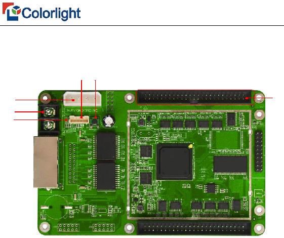
Dual 50P pins |
Connected to all display HUB boards |
|
|
|
|
|
|
2、Indicator Light functions
Red: ON for power available
Green: ON/OFF quick flashes (about 5-10times/second) indicates that the data signal transmission is normal.
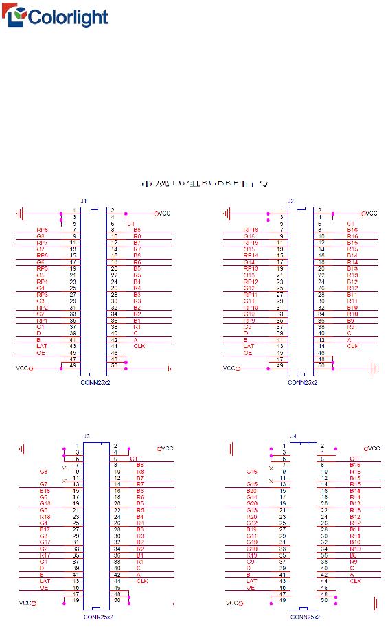
3、Definitions of 50P pins
1)16 RGBR' mode
2)20 RGB mode(Extended mode1)
www.colorlight-led.com |
version:V1.2 |
2015/10/18 |
Product Specification
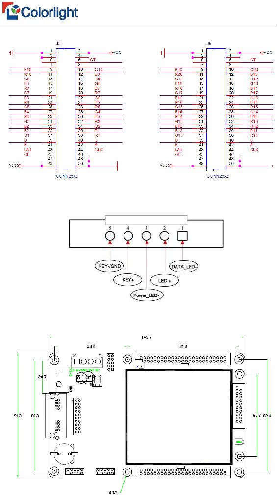
3)20 RGB mode(Extended mode2
4、External interface definition
5、Figure for receiving card size and hole position


 ⑧
⑧