
CUSTOM SUPPORT & SALE
CUSTOM SUPPORT & SALE
1) Hardware diagram
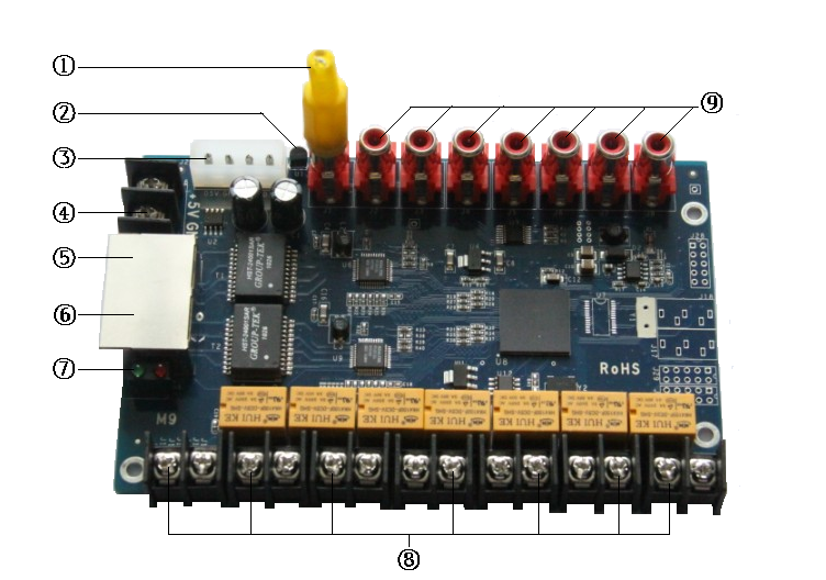
Figure 4 - 1 Multi-function Card Hardware Diagram
2) Interface descriptions
|
S/N |
Name |
Function |
Remarks |
|
1 |
Brightness sensor |
Detect and automatically control the brightness, and the minimum brightness should be 15% of the full brightness. |
Cables can be adopted to extend the distance between the sensor and the card. |
|
2 |
Temperature sensor |
It will sense the environmental real-time temperature, able to control the air-conditioning and fan switches, with the DS18B20 chip used. |
|
|
3 |
Power-in 1 |
Connect 5V power supply to power the multi-function card. |
Only one of the two should be used, it should have the function to protect against with the power reversal fault, and the voltage error shall be subject to ± 10%. |
|
4 |
Power-in 2 |
Connect 5V power supply to power the multi-function card. |
|
|
5 |
Net Port A |
Connected to sending or net card |
Regardless of input or output, the two net ports can be exchanged freely, able to support network cable upgrade. |
|
6 |
Net Port B |
Connected to receiving card |
|
|
7 |
Indicator Light |
It indicates the status of power and signal transmission. |
|
|
8 |
Control power switch interfaces J9-J15 |
Relay control, automatic power-on or off delay – Therein, J9-J12 indicate power-on and off delay linkage, and J13-J15 can control the switches individually controlled by the temperature (Attention to the relay current limit, please).
|
|
|
9 |
Extended function interfaces J2-J7 |
The voltage, humidity, sound and smoke detection can be extended, and if the function needs using, please consult our technical staff in advance. |
|
3) Diagram for power control applications
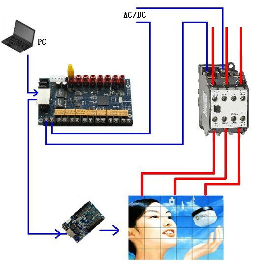
Figure 4 - 2
Contact: Lee
Phone: +86-132-6566-7728
E-mail: info@colorlitled.com
Add: Tangtou Industrial Park,Shiyan,Baoan,Shenzhen