
CUSTOM SUPPORT & SALE
CUSTOM SUPPORT & SALE
The failures of Full-color LED display are caused because of improper installation, so the installation of full-color LED display needs to be strictly followed by right steps, especially the first installation, so as to reduce errors, the following are LED display installation steps for reference to show how to connect LED display power cable.
1. Check the power supply voltage
Find the DC positive and negative to connect switching power supply, 220V power cord connected to the switching power supply, (to confirm the connection is correct, connect to the AC or NL terminal)
and then plug in the power. You Will find a power light will be bright, and then use a multimeter and DC file to measure the voltage between V + and V- to ensure that the voltage between 4.8V-5.1V, you can also cross screwdriver to adjust the voltage.
In order to reduce the heating screen to extend life, you can adjust the voltage between 4.5V-4.8. After confirmed that there is no problem with the voltage, disconnect the power supply and continue to assemble the other parts.
2. Connect the power
Turn off the power first, connect V + to the red line and V- to the black line, connect to the control card and the LED unit board respectively, and connect the black line to the control card and the power GND. The red line connects the control card's + 5V to the cell board's VCC. 1 power cord per cell board. When done, check that the connection is correct.
3. Connect the control and cell board
Use good cable, connect. Note the direction, can not be reversed. Note that the cell board has two 16-pin connectors, one for input, one for output, and the input is near the 74HC245 / 244. the input interface is connectted to control card, the output interface is connectted to the input of the next cell board.
4. Connect RJ45 network cable (data cable)
Will be done a network cable connected to the computer's network card port or send card network port, the other end connected to the control card, the remaining control card to A-B, A-B form one by one connection.
For best compatibility, the T568B standard is generally used when making straight lines. RJ45 crystal pin sequence number should be observed as follows: The front of the RJ45 plug (with copper pin side) towards down, with a copper needle facing up, one end of the connection cable facing down, from left to right 8 copper Needle number in turn is 1 ~ 8:

5. Check the connection
Again check the connection is correct, the black line is connected -V and GND. The red line is connected to + V and VCC + 5V.Red line then L, blue line then N, yellow-green line to ground
6. Detection
Turn on 220V, open the downloaded software. Under normal circumstances, the power light, flashing control card, led display screen will be displayed. If it is not normal, please check the connection again. Or check the error repair. Set screen parameters, send subtitles. Specific reference to the software instructions.
Contact us to customize LED display screen for your requirement now.
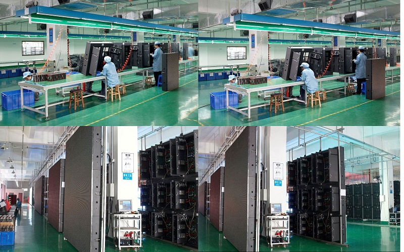
Why Choose Colorlight LED To Be Your Partner ? 12 Years Experience on Led Display Screen Manufacturing. Excellent after-sale service to meet your standards of excellence. 3 Years High Quality Warranty provided. 5% Spare Parts for Your Order Replacement. Convenient online Store (www.ledinthebox.com) for you to order LED display parts with best Price and fast DHL shipping. High Quality With Global Standards,CE EMC-B,RoHs,FCC,UL Certificated.
Contact: Lee
Phone: +86-132-6566-7728
E-mail: info@colorlitled.com
Add: Tangtou Industrial Park,Shiyan,Baoan,Shenzhen